The newest product from Josh Stewart’s Speeduino project is finally a production product. It has been in development for over a year. There were four Alpha versions and two or three Beta versions. The chip shortage has affected delivery so I feel very fortunate to have scored one of the first available. Josh’s initial order for 100 boards was made in March 2021 and it was cut back to 50 boards and delivered to him in Australia in August. Mine is bought and paid for and I have a tracking number. It should be here in a couple of weeks now.
Here are the specs straight from the documentation:
Dropbear ECU
The Dropbear is an 8 fuel + 8 ignition ECU that is currently in testing prior to a full production release. It is powered by the high speed Teensy 3.5 board and is designed to be a complete unit out of the box.
Features
- 8x high impedance injector drivers
- 8x 5v/12v coil pre-drivers (For use with igniters/smart coils)
- 6x medium current (2A) outputs
- 7x analog inputs
- 4x digital inputs
- CAN transceiver
- Onboard VR conditioner
- Swappable internal MAP sensors
- Onboard baro sensor
- Optional stepper motor driver
Board Configuration
The Dropbear board contains 4 switches and 1 DIP switch pair that can be used to change the setup of the ECU.
Crank/Cam inputs
The ECU contains a dual onboard conditioner that can can be used with VR sensors. The selection between Hall/Optical sensors and VR sensors is made via a pair of switches, one each for the crank and cam. These can be selected independently for setups that use one of each sensor type.
When set for Hall sensors, this input will work with both the traditional ground switching sensor (the pullup resistor is on the board and does not need to be added) or a 0-12v signal as used on some GM vehicles.
Crank filter
The board includes a variable hardware filter on the crank input that can be used to adjust the amount of capacitor filtering being used on this signal. This is designated SW4 or SW3 on the PCB and operates on both Hall and VR inputs.
Changing this filter from the default setting (On/On) is not required in most cases. It should only be considered if the trigger is utilising 60+ teeth at crank speed.
The switches come with an insulating Kapton seal on them that must be removed before the switches can be adjusted. If not adjusting filter this tape should be left in place.
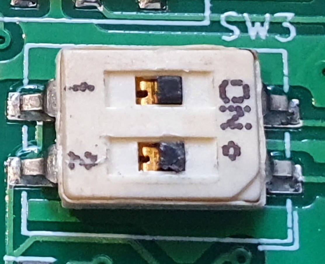
Recommended values for the filters are shown below (By default both switches will be in the On position):
| Tooth count (at crank speed) | Switch 1 | Switch 2 |
|---|---|---|
| Less than 60 | On | On |
| 60-100 | On | Off |
| 100+ | Off | On |
Both switches can be set to off, however doing so will disable all hardware filtering. This can be useful when performing bench testing with a stim, but is not recommend for real world use
MAP Selector
The Dropbear board uses a removable MAP card containing the sensor and a short hose running to the bulkhead connector on the enclosure. Currently only the default 0-250kpa sensor board is available, with higher range boards to be made available in the future. To use this MAP card, select the Int. (Internal) option on the MAP switch.
If you wish to use an external MAP sensor located in the engine bay, this switch should be to to Ext. and the sensors signal line should be connected to pin C8 on the Black connector. The MAP card can be left in place or removed when the Ext. option is used.
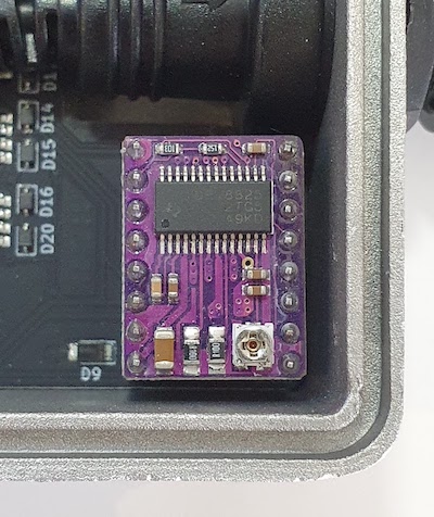
Stepper Driver
By default the Dropbear unit is designed for use with PWM idle valves, however an optional stepper motor driver can be fitted.
Please note that using the stepper driver requires pins C3 through C6 on the grey connector. Other output functions cannot use these pins when a stepper driver is installed
The board has a socket to install a standard DRV8825 stepper motor driver if required. It should be installed in the following orientation if needed:
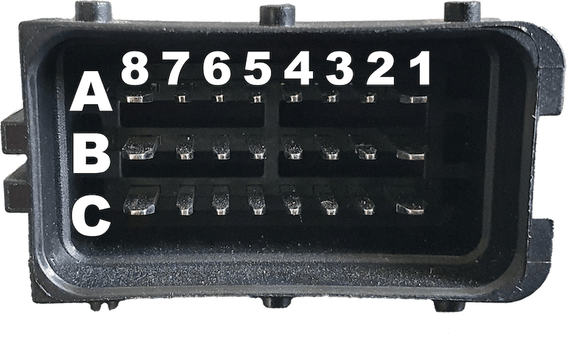
Pin out
The Dropbear ECU uses 2x 24 pin Delphi Sicma connectors. The connectors are keyed and will only connect to the matching colour loom plug.
Black Connector
| Pin | Direction | Max Current | Purpose | Comment |
|---|---|---|---|---|
| A1 | Input | 5A | Switched 12v | Main power input. Connect to switched 12v power via 5A fuse |
| A2 | Input | 15A | Power Ground | Connect to battery negative. |
| A3 | Output | 80mA | Sensor reference | Used for sensors requiring a 5v reference (Eg TPS). Do not use for powering offboard systems. |
| A4 | N/A | N/A | Not used. | |
| A5 | Input | N/A | Spare Digital In 2 | 12v or Ground switching digital input. Can be used for VSS, Idle Up etc. MCU pin #22 in TunerStudio |
| A6 | Both | N/A | CAN L | CAN L connection |
| A7 | Both | N/A | CAN H | CAN H connection |
| A8 | Input | 15A | Power Ground | Connect to battery negative. |
| B1 | Output | 100mA | Tacho | 12v square wave output for use as input to a tachometer |
| B2 | Input | N/A | Crank Primary | Primary crank sensor (CKP) input. Can be 12v, Ground switching or the positive wire of a VR sensor. See Crank/Cam Inputs section |
| B3 | Input | N/A | Crank Negative | Only used with a VR sensor. Connect to negative side of VR crank sensor. See Crank/Cam Inputs section |
| B4 | Input | N/A | Cam Primary | Cam sensor (CMP) primary input. Can be 12v, Ground switching or the positive wire of a VR sensor. See Crank/Cam Inputs section |
| B5 | Input | N/A | Cam Negative | Only used with a VR sensor. Connect to negative side of VR cam sensor. See Crank/Cam Inputs section |
| B6 | Input | N/A | Spare Digital 1 | 12v or Ground switching digital input. Can be used for VSS, Idle Up etc. MCU pin #23 in TunerStudio |
| B7 | Input | N/A | Clutch input. | Ground switching digital input that goes to ground when clutch is engaged. Do not feed 12v on this input |
| B8 | Input | N/A | Flex sensor | Signal wire from GM/Continental Flex sensor. |
| C1 | Output | N/A | Analog ground | Ground reference for use by sensors such as TPS, IAT, CLT. Do not use for powering offboard controllers |
| C2 | Input | N/A | Spare Analog 1 | Spare analog input for use with 0-5v sensors such as fuel pressure/temperature, oil pressure etc. MCU pin A17 in TunerStudio |
| C3 | Input | N/A | Spare Analog 2 | Spare analog input for use with 0-5v sensors such as fuel pressure/temperature, oil pressure etc. MCU pin A18 in TunerStudio |
| C4 | Input | N/A | O2 Sensor | Connect to the 0-5v signal wire of external wideband controller. Can also be used with 0-1v output from narrowband sensor however wideband is strongly recommended |
| C5 | Input | N/A | Coolant Sensor | Connect to one side of 2 wire coolant sensor (CLT). Other side of sensor connected to pin C1 |
| C6 | Input | N/A | Inlet Air Sensor | Connect to one side of 2 wire inlet air temp sensor (IAT). Other side of sensor connected to pin C1 |
| C7 | Input | N/A | Throttle Sensor | Connect to signal line of variable throttle position sensor (TPS). Other pins of sensor should connect to C1 and A3 |
| C8 | Input | N/A | External MAP Sensor | Signal line if using external MAP sensor. Input should be 0-5v and MAP source switch should be set to ‘Ext.’. See MAP Selection section for more details. If using internal sensor this pin should be left unconnected. |
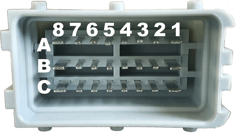
Grey Connector
| Pin | Direction | Max Current | Purpose | Comment |
|---|---|---|---|---|
| A1 | Output | 2A | Injector 1 | Injector 1 output |
| A2 | Output | 2A | Injector 2 | Injector 2 output |
| A3 | Output | 2A | Injector 3 | Injector 3 output |
| A4 | Output | 2A | Injector 4 | Injector 4 output |
| A5 | Output | 2A | Injector 5 | Injector 5 output |
| A6 | Output | 2A | Injector 6 | Injector 6 output |
| A7 | Output | 2A | Injector 7 | Injector 7 output |
| A8 | Output | 2A | Injector 8 | Injector 8 output |
| B1 | Output | 100mA | Ignition 1 | Ignition 1 output. 5v or 12v depending on switch selection. Do not connect directly to high current coils, only connect to igniter or ‘smart’ coil |
| B2 | Output | 100mA | Ignition 2 | Ignition 2 output. 5v or 12v depending on switch selection. Do not connect directly to high current coils, only connect to igniter or ‘smart’ coil |
| B3 | Output | 100mA | Ignition 3 | Ignition 3 output. 5v or 12v depending on switch selection. Do not connect directly to high current coils, only connect to igniter or ‘smart’ coil |
| B4 | Output | 100mA | Ignition 4 | Ignition 4 output. 5v or 12v depending on switch selection. Do not connect directly to high current coils, only connect to igniter or ‘smart’ coil |
| B5 | Output | 100mA | Ignition 5 | Ignition 5 output. 5v or 12v depending on switch selection. Do not connect directly to high current coils, only connect to igniter or ‘smart’ coil |
| B6 | Output | 100mA | Ignition 6 | Ignition 6 output. 5v or 12v depending on switch selection. Do not connect directly to high current coils, only connect to igniter or ‘smart’ coil |
| B7 | Output | 100mA | Ignition 7 | Ignition 7 output. 5v or 12v depending on switch selection. Do not connect directly to high current coils, only connect to igniter or ‘smart’ coil |
| B8 | Output | 100mA | Ignition 8 | Ignition 8 output. 5v or 12v depending on switch selection. Do not connect directly to high current coils, only connect to igniter or ‘smart’ coil |
| C1 | Output | 2A | Boost | Ground switching output for use with boost control solenoid |
| C2 | Output | 2A | Fan. | Ground switching output for triggering a fan relay. Do not drive fan directly from this pin, use only with relay |
| C3 | Output | 2A | Spare 2/Stepper-B2 | Can be used either as ground switching output for general purpose use or 12v output if using a stepper idle control (Requires stepper driver to be fitted, see Stepper Driver) |
| C4 | Output | 2A | Idle/Stepper-B1 | Can be used either as ground switching idle output (For use with PWM valves) or 12v output if using a stepper idle control (Requires stepper driver to be fitted, see Stepper Driver) |
| C5 | Output | 2A | VVT/Stepper-A1. | Can be used either as ground switching VVT output or 12v output if using a stepper idle control (Requires stepper driver to be fitted, see Stepper Driver) |
| C6 | Output | 2A | Spare 1/Stepper-A2 | Can be used either as ground switching output for general purpose use or 12v output if using a stepper idle control (Requires stepper driver to be fitted, see Stepper Driver) |
| C7 | Output | 1.5A | Fuel Pump | Ground switching output for triggering fuel pump relay. Do not drive pump directly from this pin, use only with relay |
| C8 | Input | 15A | Power Ground | Connect to battery negative. |