Using the TSRM and TEWD conventions for numbering pins, these are the three connectors on the pre-1989 “yellow plug” ECU for a manual transmission. This is not a change from the original configuration. It is only a documentation correction to make things easier for me to use. The Toyota documentation numbers pins left to right and top to bottom. Commonly published 3rd party documentation does not follow the Toyota convention.
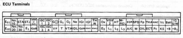
Pin #      Symbol          Terminal

1          E01             POWER GROUND
2          No. 10          INJECTOR (No. 1 and 4)
3          STA             STARTER SWITCH
4          STJ             COLD START INJECTOR
5          * N/C           CLUTCH SWITCH (M/T)
6          E02             POWER GROUND
7          No. 20          INJECTOR (No. 2 and 6)
8          No. 30          INJECTOR (No. 3 and 5)
9          E1              COMPUTER GROUND
10        IGdB             IGNITER

* For cruise Control << Don’t understand why N/C as we have Cruise Control
Pin #      Symbol          Terminal

1          ISC1            ISC MOTOR NO. 1 COIL
2          ISC2            ISC MOTOR NO. 2 COIL
3          G-              CAM POSITION SENSOR
4          G1              CAM POSITION SENSOR
5          G2              CAM POSITION SENSOR
6          Ne              CAM POSITION SENSOR
7          IG1             IGNITER
8          IGf             IGNITER
9          THW             WATER TEMP. SENSOR
10         ISC3            ISC MOTOR NO. 3 COIL
11         ISC4            ISC MOTOR NO, 4 COIL
12         Vf              CHECK CONNECTOR
13         T               CHECK CONNECTOR
14         VTA             THROTTLE POSITION SENSOR
15         IDL             THROTTLE POSITION SENSOR
16         IGdA            IGNITER
17         KNK1            KNOCK SENSOR
18         KNK2            KNOCK SENSOR
Pin #      Symbol          Terminal

1          Ox              OXYGEN SENSOR
2          VSV2            VSV (FPU)
3          HT              OXGEN SENSOR
4          M-REL           EF| MAIN RELAY (COIL)
5          EGR             VSV (EGR)
6          SPD             SPEEDOMETER
7          Fp              FUEL PUMP RELAY
8          THA             AIR TEMP SENSOR
9          HAC             ALTITUDE COMPENSATION SENSOR
10         Vc              AIR FLOW METER
11         Batt            BATTERY
12         IG S/W          IGNITION SWITCH
13         E2              SENSOR GROUND
14         L1              ECT COMPUTER
15         L2              ECT COMPUTER
16         L3              ECT COMPUTER
17         A/C             A/C MAGNETIC SWITCH
18         W               WARNING LIGHT
19         OIL             OIL PRESSURE SWITCH
20         ECT             ECT COMPUTER
21         Fc              CIRCUIT OPENING RELAY
22         Ks              AIR FLOW METER
23         +B              EFI MAIN RELAY
24         +B1             EFI MAIN RELAY

I find no place for the NSW as this is a Manual Transmission ECU

NSW               NEUTRAL START SWITCH (A/T)

The following connector exists in the harness but does not connect to the ECU

Pin #    Symbol            Terminal

xx        TIL              TURBO INDICATOR
xx        DFG              DEFOGGER RELAY
xx        LP               HEADLIGHT RELAY

The 4th yellow connector with the flying lead will not be used.